About this deal
As said in the introduction, in this step we won’t explain how to solder because it would make the tutorial too long and, above all, because we already covered this topic in our first tutorial. So, take a look at it if you want to know more about soldering. If you buy your own FTDI chip, go for something that has two serial ports, e.g. FTDI FT2232H, those are often used as JTAG interface with an additional serial port, too.
I am a hobbyist, not an EE, with about a dozen Linux SBCs and a half a dozen WiFi switches and access points, two of them in active use running OpenWRT. An Odroid HC1 I have has an UART at 1.8V logic levels; it is probably the most ornery one I have. I need 1.8V and 3.3V, and occasionally find that 2.8V-3.0V and 3.8-4V would also be useful, so basically I want "whatever the device uses, between 1.6 and 5.3 V" or so. I wanted to try echolink and I found that this interface worked perfectly except Echolink likes the serial PTT option. I have that model, too. That board is a mistake by design. It was very infuriating to find out the power supply was changing, while the levels on the data pins voltage were always 0..5V.
the connector to be soldered on the part of the analog inputs is too wide, thin it slightly by rubbing it on sandpaper keeping, as already mentioned, the Arduino inserted on the two connectors, solder the 4 pads in the corners. Why only these 4 points? Because the breadboard is made of plastic and excessive heat could damage it
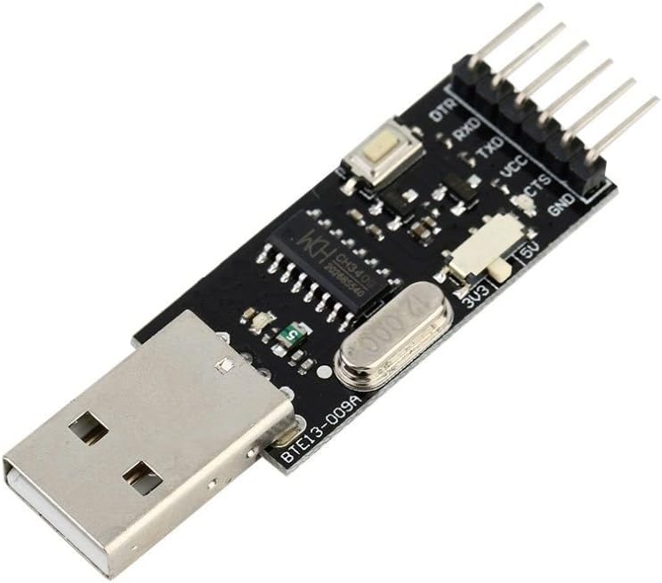
You want to use unidirectional voltage level translators or isolators for UART and SPI, and not bidirectional ones, as the latter tend to have glitches (in the low level signal part, when the direction sensing circuitry isn't sure of what is going on) in this kind of use that can cause transmission errors. So, I'd say forget TXB chips, and all bidirectional voltage level conversion chips. Before starting, we specify that this tutorial can be used to learn how to install the drivers of the CH340G module (Serial – USB converter), on which the communication between the Arduino mini and the PC is based. I have also found that these drivers work fine when connecting the LoLin NodeMCU V3 to my Windows 7 PC (I had to do nothing, since I had already loaded the drivers for my cheap Chinese Arduino Nano clones). I suspect the same will be true for the Amica v0.9 (yellow or blue PCB) NodeMCUs (both considered out-dated) and the DoIt/SmartArduino brand NodeMCU V2. Both of these boards also use a WCH CH340G USB-to-UART bridge chip. But it doesn’t end here! That’s were the Power Cutter comes in. Thanks to Talpa PCB retrace of the BTE13-010 I was able to elaborate an evil power saving plan:The NODEMCU “Arduino friendly” pin names (D0 thru D8, plus RX and TX) don’t correspond with the actual ESP8266 GPIO pin numbers, so you have to make special arrangements to map the “D1”, “D2”, etc names to the actual GPIO pin numbers. There are a few ways to do this. Look at the Fritzing diagram above or follow the instructions below to connect the Arduino mini clone to the Serial to USB converter: BTE13-010--------------CH340G soldering material and equipment (in this regard you can watch our tutorial Yet another tutorial on how to solder)
The access points normally are running at 115kbit and will need reliable transfer for binary uploads.Often the FTDI based ones are preferred. The FTDI chip is very expensive in comparison with other USB to TTL bridges, but they are often preferred. So look for FTDI when searching USB to TTL. Often FTDI ones use fake clones instead of the genuine and expensive FTDI, so if it's too cheap then it's probably not genuine FTDI.
Before connecting the Serial – USB converter, make sure that the switch is positioned on the appropriate voltage value which can be 3.3V or 5V depending on the model of your Arduino. Ours works at 5V and 3.3V interchangeably. However, if you look at the CH340 datasheet, the same board can be modified to change both the Vcc and the data pins voltage from the same switch, but you'll have to cut a few traces and rewire. I modified mine, but can not find the schematic with the changes right now. It was only a few traces to rewire as seen in the pics, and now it switches both the power and the data levels.In the IDE, go to File/Examples/Basics/Blink and load the sketch. If you have performed the previous steps correctly, the IDE should be able to communicate with the Arduino and upload the sketch. Eventually you will see LED 13 (on the board, blue) flashing once per second. Blue LED on board flashes once per second (with “blink” sketch) Soldering headers can be pretty easy if you take advantage of a breadboard. Place them on it and then put Arduino over connectors. The first one I killed when I used a USB TTL adapter that I believe kept the TTL signal level at 5V even when selecting 3.3V.
 Great Deal